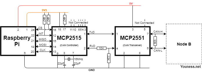

Mode – The trigger mode as specified above (FALLING) Interrupt – This is the interrupt source, either 0 for INT0 įunction – The function to call when the interrupt occurs(MCP2515_ISR) Here we are using this function with following three parameteres: When configuring our external interrupt we will use the Arduino library function attachInterrupt(interrupt, function, mode). Active High is maintained in the INT pin of MCP2515 and when new data is available it changes to low for a moment this can be captured by the Arduino external interrupt. So, digital pin 2 will be connected to MCP2515 INT pin. RISING – a rising edge of a level triggerįALLING – a falling edge of a level triggerįor this tutorial we will be using a FALLING trigger mode.

The Atmega8 supports four trigger modes for external interrupts: The Arduino Mega has an additional four INTR2-INTR5.Ītmega8,Atmega168 and Atmega328 micro-controller on the Arduino boards have two external interrupts available: INT0 and INT1, located on digital pins 2 and 3 respectively. There are four available functions for controlling interrupts with Arduino: attachInterrupt (), detachInterrupt (), interrupts (), and noInterrupts ().Most Arduino boards have two external interrupts: INTR0 and INTR1. Interrupts cvan be enabled by setting or clearing bits in internal registers. The advantage of hardware interrupts is the Arduino will not waste most of its time “polling” or constantly checking the status of an IO pin.Īrduino has a number of interrupt sources, most of them tied into internal hardware modules such as timers and comparators, while some are tied into external hardware pins.
#Stm32 driver for mcp 2515 how to#
It is assumed that the reader has gone through the project how to get started with the Arduino and Cloning of Arduino and done all the things discussed in it. The board also provides two external interrupt pins. The advantage of using this board is because it is very breadboard friendly and occupies very less space of a typical breadboard. This article discusses the external interrupt based on the Arduino pro-mini board or Arduino clone which is programmed using the Arduino IDE version 1.0.1 downloaded for windows. Two Arduino Board or Arduino clone(Here is a guide if you need)

The Arduino will stop its current processing and start executing the ISR once an interrupt occurs. This article will give information about how Arduino external interrupt can be used to get the data from MCP2515 CAN controllers to save the time wastage in polling method for the data availability from CAN controller.ġ.
#Stm32 driver for mcp 2515 code#
The block of code which is written to process by an interrupt occurrence is called an Interrupt Service Routine (ISR). The interrupt is a method to divert the Arduino from current block code execution to do another block of codes that needs immediate processing. The Arduino board also includes pins which can be used as external interrupt pins.


 0 kommentar(er)
